Lecture 03: Shading (slides)Learning ObjectivesBy the end of this lecture, you will be able to:
|  |
Lecture 03: Shading (slides)Learning ObjectivesBy the end of this lecture, you will be able to:
| |
Today we will take the leap from rendering flat 2d-like scenes into making them look more 3d-like. In our previous ray tracing exercises & lab, we just set the pixel color to the color of the closest object intersected by a ray. Now, we'll use some more information about the surface being intersected and place some virtual lights to add shading to our scenes.
Shading is the process of painting brighter spots on a surface that face the light and darker spots where the surface is either not directly facing a light or is obscured by another object. In the picture at the top-right of this page, suppose a light source is located somewhere to the left of the apple. The left side of the apple looks brighter whereas the right-side looks darker. Our main goal for today is to be able to mathematically (and programmatically) calculate this. It also opens the door for more complicated techniques for modeling reflective and refractive materials.
The colors that we see in the room around us are the result of light bouncing off the walls, off of other objects and ultimately into our eye. This final color depends on how much light is absorbed by an object, and how much is then reflected. For example, a red apple will primarily reflect the red components and absorb the blue and green components of the light.
To describe this mathematically, we first need to model how much light is coming from a light source (towards the apple), and then use properties of the apple to determine how much light is reflected back to our eye. These are the two main ingredients we need: setting up light sources and describing the materials of our objects.
Warning: We'll quantify and reason through how some of the equations we use relate to reality, but shading might sound like a bunch of hacks. All we care about is making our objects look a certain way, which will involve tuning a lot of the parameters in our equations. Here's an excerpt from the FAQ section of Fundamentals of Computer Graphics:

During the day, we see things outside because of the sun. At night, we need lamps to see the objects around us, and the light a lamp emits controls the lighting in the room. For example, consider the cactus and flamingo lamps below. The cactus lamp makes the rest of the room look kind of green, whereas the flamingo lamp makes the room look pink.


This raises the first property of light sources that we need to consider: the color of the light emitted. We can also illuminate our scenes without a direct source of light. For example, when the sun is rising over the horizon, we may not be able to see the sun yet, but it is still providing some light to our surroundings. We'll model this as an ambient term which we'll denote as
The intensity of the light generally depends on how far the light source is, which involves calculating the distance from our object to the specific location of the light source. However, lights that are really far away (like the sun), this distance is essentially infinite. Most of the stuff we do will only require the direction of the light, which you can either specify directly (like you would do for the sun), or calculate from your surface to the location of the light.
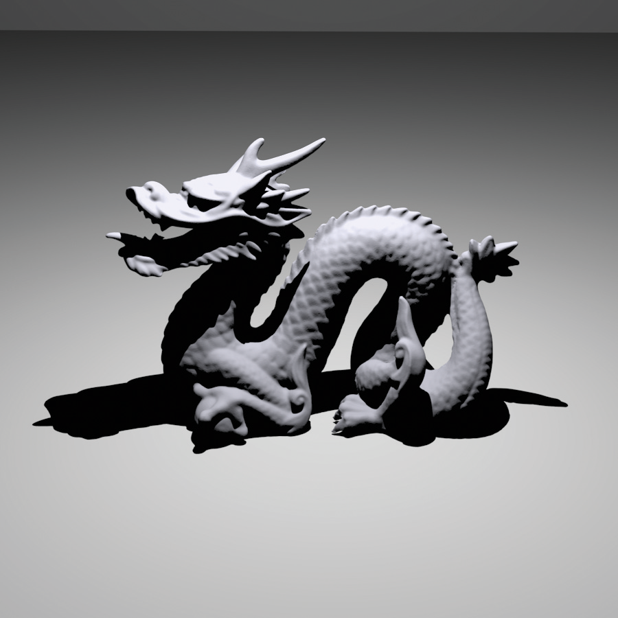
Please note, however, that real-life light sources are not just points (for a location) or directions. There is an area of the light source, for example, the area of rectangular or ring lights - even the surface area of a simple light bulb should be accounted for. Area light sources produce shadows that account for both an umbra and penumbra. The left image below is illuminated with a point source - notice the hard drop-off in the shadows. The image on the right (source) is illuminated with an area light, which has softer transitions of the shadows and looks much more realistic.
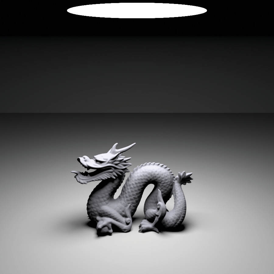
However, area light sources are much more difficult (and much more computationally intensive) to model with the direct illumination techniques we'll use. Instead we'll just focus on either point light sources or directional lights. We'll also assume that the intensity of the light is constant in our scenes (i.e. it does not depend on the distance from the light to our surfaces).
The light energy coming from a source will hit the objects in our scenes and either get absorbed or reflected. How light is reflected, and how much depends on the material properties of the object. The pigments in a material determine which color components of light are reflected back to our eyes. For example, in the image below (source), the blue component of incoming light is reflected, whereas the red and green components are absorbed.
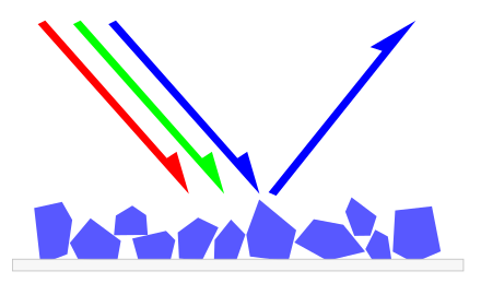
The fraction of light energy diffusely reflected by an object is called the albedo. This reflection ratio varies for each color component, so the albedo has components for all three RGB values.
In the picture above, the blue light seems to reflect perfectly off of the material. However, light will reflect in different ways for different materials. For example, matte-like materials will diffuse light in all directions across a surface. Plastic-like materials will also have shiny spots that highlight the reflected light, similar to how mirrors reflect light. Finally, translucent materials allow light to change directions (refract) when they hit the material.
We'll break up the light at a surface point into various contributions and add them up. Why are we allowed to do add them up? Light is a wave that obeys something called the principle of superposition. Our final color will be the superposition of an ambient term, diffuse term and specular term (for reflections).
Source lights (like a lamp or the sun) have a color which will be denoted with the symbol
Each of these contributions is an RGB value between 0 and 1, so it's very possible that we get components bigger than 1 when we add them up. It's a good idea to clamp the final value so it has a maximum of 1.
The ambient term is influenced by the color of the ambient light
It should be noted that the color components are multiplied component-wise:
Note that the vec3.multiply function in glMatrix will multiply vectors component-wise.
Matte-like materials diffuse the incoming light in all directions across their surfaces. The intensity of the diffusion can be modeled using Lambert's law which states that the diffused light intensity is proportional to how much the normal vector of a surface aligns with the direction to the light source. This can be quantified by looking at the cosine of the angle between the light direction and the normal vector or, equivalently, the dot product between the aforementioned vectors. We then have
|
$$
I_d \propto \vec{n}\cdot\vec{l} \quad \leftrightarrow \quad I_d \propto \cos\theta
$$
where |
  Fundamentals of Computer Graphics (Shirley, 5th Ed.) |
We've used the word "normal" a few times now, which is the vector perpendicular to a surface, and pointing "outside" of the surface. This is something we'll need to compute at each point where a ray intersects our model surfaces. So far, we've seen spheres and triangles. How do we calculate the normal vector for each of these?
Some objects look kind of "shiny" or "glossy". For example, in the following picture, there is a glossy highlight on each ball, which is a reflection of some light in the room:

This highlight can be added to our color by using the Phong lighting model, named after a graduate student at the University of Utah back in the 1970s. Ideally we would like to see a fuzzy highlight when our view direction is directly aligned with the reflection direction
Similar to our previous reasoning, the highlight will be strongest when our view direction (
The color we see in the highlight is the light color
There's a lot that goes into these calculations, so let's take a moment to practice with all the equations. In the editor below, please complete the shader function which should add up the ambient, diffuse and specular terms to make the sphere rendering below look more 3d. Please feel free to adjust some of the coefficients such as ca, cl, km, ks and p! The canvas is not configured to run automatically when you type (since ray tracing can be slow), so please click the Render button to update the scene with your shader function.
const shader = function(surfacePosition, surfaceNormal, lightPosition, eyePosition) {
  const ca = vec3.fromValues(0.2, 0.2, 0.2);
  const cl = vec3.fromValues(1, 1, 1);
  const km = vec3.fromValues(0.9, 0.5, 0.5);
  const ks = km;

  // ambient term
  const Ia = vec3.multiply(vec3.create(), km, ca);

  // diffuse term
  const l = vec3.normalize(vec3.create(), vec3.subtract(vec3.create(), lightPosition, surfacePosition));
  const n_dot_l = vec3.dot(surfaceNormal, l);
  const diffusion = Math.max(0.0, n_dot_l);
  const Id = vec3.multiply(vec3.create(), km, vec3.scale(vec3.create(), cl, diffusion));

  // specular term
  const v = vec3.normalize(vec3.create(), vec3.subtract(vec3.create(), eyePosition, surfacePosition));
  let reflectDirection = vec3.negate(vec3.create(), l);
  reflectDirection = vec3.scaleAndAdd(vec3.create(), reflectDirection, surfaceNormal, n_dot_l * 2.0);
  const p = 32;
  const specular = Math.pow(Math.max(0.0, vec3.dot(v, reflectDirection)), p);
  const Is = vec3.multiply(vec3.create(), ks, vec3.scale(vec3.create(), cl, specular));
  return vec3.add(vec3.create(), Ia, vec3.add(vec3.create(), Id, Is));
}
Shadows occur because there is something blocking a point from the light source. This means that if we drew a straight line from a point to the light source, then that straight line would intersect something in our scene. Luckily, we already know how to intersect our objects with straight lines, so we'll just recycle those functions! We'll then need to slightly refactor how we shade a point when it's in a shadow.
When you detect that your primary camera ray (the one from the eye through a pixel) intersects an object in your scene, then the first thing you should do is set that pixel color to the ambient color contribution (

In the image above, the primary camera rays are drawn in blue and the secondary rays to the light source (at the top left of the scene) are drawn in black.
In general it's a good idea to write a function that will determine if an arbitrary ray will intersect any object in your scene, and return information about the closest intersection point, as well as which object (and which material) is intersected.
If you look in the mirror at an angle, you'll see the objects that are reflected at the same angle with respect to the mirror normal direction. So if you drew a ray from your eye to the point on the mirror you're looking at, and then reflected that ray, whatever this reflected ray hits is what we see. Again, we have all the machinery to model this in our ray tracer (with a little more refactoring)!
When you detect that your primary camera ray hits a mirror-like object in your scene, compute the reflection direction

What if this second intersection point is also a mirror? Send another ray! Keep doing that until you either hit an object that is not a mirror, or nothing is intersected, in which case you can use the sky color.
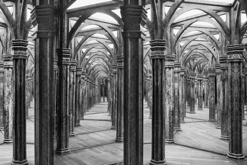
This sounds a lot like recursion, and it is. Recall that with a recursive function, though, we need a base case. Here, we might never reach the base case of either not intersecting anything or intersecting a non-mirror. Imagine a scene made entirely of mirrors (as in the house of mirrors in the rightmost image above) - we might keep sending rays forever! In practice, you should put a limit on the number of secondary rays you can send for a single pixel, which is the failure-proof base case for a recursive ray tracer.
An alternative is to just write the recursion as a for loop over the number of allowed secondary rays (or "bounces"). If one of these secondary rays hits the sky or a non-reflective material, just break the loop. Why would we do this instead of recursion? For one, it might be easier to debug. More practically, if you write a ray tracer on the GPU, GPUs are not very good at recursion.
Here is some pseudocode for how we might write a recursive ray tracer using what we learned today. The following computeColor function is called for each pixel and the initial ray is the primary camera ray.
function computeColor(ray, currentDepth)
  1.  color = background sky color
  2.  if (currentDepth > maxDepth) return color
  3.  if (ray does not intersect any object) return color
  4.  color = Ia // initialize to ambient color term
  5.  shadowRay = new ray from intersection point to light
  6.  if (shadowRay intersects any object) return color
  7.  color += Id + Is // add diffuse and specular terms
  8.  if (intersection object is mirror)
  9.    reflectedRay = new ray from intersection point in reflection direction
  10.   color += computeColor(reflectedRay, currentDepth + 1)
  11. return color
As you can see, we might need a more general function to determine if an arbitrary ray (camera, shadow or secondary) intersects an object in the scene. We will also need some information from this intersection function that returns (1) the intersection point, (2) the surface normal at the intersection point and (3) the material of the intersected object.
© Philip Claude Caplan, 2023 (Last updated: 2023-09-27)